I’m doing some projection mapping on a pretty complex model using three projectors. Right now I’m sorting meshes by their normals in vvvv code to decide which ones to show in each projectors’ renderer. Seems like this would be something a shader could handle much better. Basic idea is to only paint faces that are within some angle of a vector to the projector, leaving all others black.
Is something like this already out there? I figure if not, something like a Gouraud shader could be hacked to do this. Any pointers greatly appreciated!
OK, but how (or rather where) in the shader to decide where to set the vertex color? I’d need to look at the vertex normals, compare them to the vector to the projector (I figure similar to comparing then to light direction in Gouraud) and then set them to black if outside some angle from the projector vector. I’m just not familiar enough with DX11 shaders to know where to go start hacking… Or if such a shader already exists. Thanks!
Well vertex colors you would use in case you want to do that by hand in 3d modeling software, because there is many factors in such calculation… Like if it is already has color, like the normal didn’t pass threshold for any of the projectors and so on…
Normally i would do test on vertex shader and output something to pixel shader that will decide whether it need’s to color it, but in your case i think you need to do a gsfx with buffered spread of view projection, compare each triangle with all 3, then add a channel to geometry and pass it to next shader with extra semantics…
this gonna take a bit to compose this example, meanwhile:
you got struct VS_IN in there
struct vsInputTextured
{
float4 posObject : POSITION;
float4 normalObject : NORMAL;
float4 uv: TEXCOORD0;
};
struct psInputTextured
{
float4 posScreen : SV_Position;
float4 uv: TEXCOORD0;
float4 Diffuse: COLOR0;
float4 Specular: COLOR1;
};
ok so we add to psInputTextured custom variable
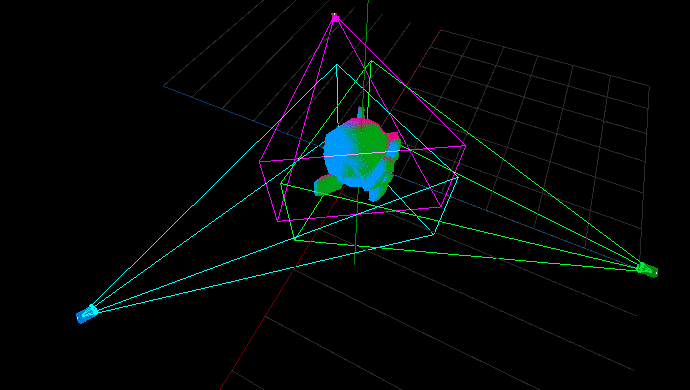
input is the view transform of all three projectors and color to be assigned to the vertex that has normal most perpendicular to that projector (larges z element of the vertex normal in viewspace).
as you can see there are few limitations to this approach - it would not work with concave objects as it does not check for occlusions. i would guess that there are also way to many blending seams to give you compelling results.
@antokhio Thanks for the pointer, I did some poking around in the vertex shader of GouraudDirectional and got something more or less working by taking the dot product of the “light” (projector facing) direction and the vertex normal, and setting the vertex color to black if it was less than some specifiable amount. Would be better to specify an angle, but didn’t know the right calls for that off the top of my head.
@id144 Whoa bro! Fabulous example, very educational! Let me digest that some more and fool around with it.
@id144 - Your shader has in fact been very educational! At first I did not see why you had it handling all three projectors at once, until I realized that if for the overview you just tried to combine the layers from the three separate shaders, the black areas from the highest priority one would hide the other layers.
After fooling around with it a bit, there are some things that I think would make it work better. For example, when you consider projector field of view and position, the relative angles to each projector can vary quite a bit; so it can make a big difference that instead of using the view angle for comparison, the angle to the vertex from the projector position was used. Also if relative distance was considered it may help as well.
I’ll poke around on this some more and see how that will work. I’m dealing with a very large model made by some architecture grad students who are not really 3D modelers, and have found manually optimizing that model for projection is impossible (have you tried Rhino? Just poke me in the eyes with sharp sticks!), plus I think having a full-auto way to do this will be very handy for folks. Thanks again!
Thanks @mediadog, I’m glad I could help. The solution should also deal with fall-off gamma correction of the edge blending. Calculating the projection area is good idea. Lot of techniques could be done in screenspace as in a postprocess. Big challenge is to find exact location of the three projectors (do it after they are on for at least half an hour). HTC Vive tracking could help greatly.
I’m using Rhino often, but for the videomapping on complex geometries I like tandem of Reality Capture / Blender / MeshLab. You need good retopologization and UV mapping in this case.
We had this workshop with students where we tried projection on complex geometries. Of course, these are techniques well explored years ago by @elliotwoods who I know also dealt with project where he videomapped complex and moving geometry and he developed projection handover techniques.
This technique first runs a simulation (in VVVV) of how each projector covers the scene, this gives the available brightness per unit area of the scene per projector. Then it attempts to achieve uniform brightness by assigning brightness from different projectors (prioritising ‘good’ coverage where available)