currently I am struggeling with the electronics in my following project. I hope you can help me. Thanks for any advices!
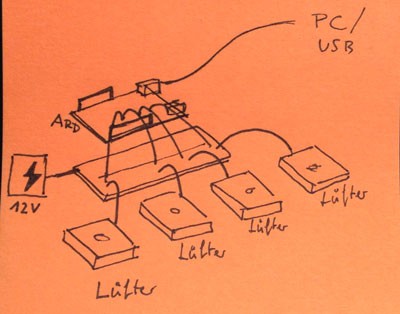
I would like to control a bunch of computer fans (5V or 12V) by using an Arduino UNO (+ external 12V power supply) and vvvv with the StandardFirmata. But I am struggeling with the electronics.
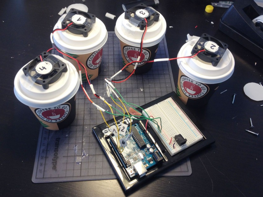
There is already a working prototype with 4x 5V Fans (each 2 wired), but I can’t manage them to be controlled with vvvv. The fans start to rotate but I don’t know how to control them.
Do you have an example for a working, easy circuit? This would be awesome!
Shall I use 12V fans (3 wired) or 5V fans (2 wired)?
Which transistors, resistors are best for this case?
Finally I could manage to run four 5 Volt fans with the Arduino. With the 12 Volt Power Input, they get super fast. I used some TO-92 Transistors. It is now possible to control the fans via Firmata and PWM:
the fans run faster, if the pwm-values are lower. 0 = fast, 1 = low/stop. How can I solve this?
the fans don’t run quiet exactly. Sometimes too fast, sometimes too slow. How can solve this problem? Maybe using some resistors? If yes, where to plug?
just to be sure: in your last picture you got 5V Fans, but a 12V power supply, they will run faster, but also probably break at some point…
Im far from being an electronics expert, so if in doubt ask google about my suggestions haha
Try a 5V Voltage source with sufficient amperage. There should be a lable on the fan stating how much current it draws. multiply that value by the voltage and if that exceeds the 0,5W of your transistor, consider buying another transistor!
make sure your transistor is made for a 5V Gate voltage… some might not fully switch on the 5V of the arduino, they need a certain threshold voltage.
Common ground is probably a good idea as well, connect the arduino ground with the voltage source ground.
And you might want to add a resistor (>10k) between gate and ground…
you are on the right track, but i think you will burn out your arduino doing this…
i will back up what soriak said… but i would do this in 2 stages for the sake of learning.
start by powering the arduino normally, then take 5v from the arduino to power the breadboard (with transistor, ONE motor, and you will prob need a resistor somewhere to be safe, prob a back-current doide aswell, but thats getting ahead of ourselves)
…and then complete the power by returning from the breadboard to the ground on the arduino.
get that working, then move on…
then try with more motors. for this i would run a seperate power supply for the motors, as you will draw too much current through the arduino and blow it up.
…so, keep the arduino powered normally and swap the 5V for a seperate supply. then keep the ground wire from the breadboard to the arduino AND also connect the breadboard ground to your 2nd power supply. this keeps a common ground between the two which is wierd, but makes sense later. (took me ages to understand that one…)
[ disclaimer - i am not an expert, just trying to pass on wot i learnt this summer ]( disclaimer - i am not an expert, just trying to pass on wot i learnt this summer )
…i would draw you a diagram, but have to go to sleep, sorry
If you need to control speed of your fans you need pwm pins (you can access 6 with Uno and 14 with Mega) . If there is no need of speed control you can use any of the arduino pin (analog also, except occupied by Serial communication with vvvv).
I suggest you to check ULN2003 IC for powering your motors. Very old and easy to use Darlington array. Everything included (no need to use external elements) and cheap as dirt. Also breadboard friendly in DIP version. Suitable for both scenarios (with/without speed control).
I’ve used a bunch of this IC to pwm control my led strips with Arduino Mega, Firmata and vvvv.
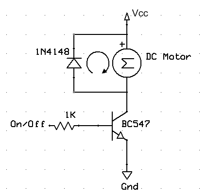
I don’t see your schematics, but something wrong. Here is the proper ones.
And the tutorial
Check your transistor pin-out and the type. You need bipolar NPN transistor.
It should be 0V at base pin (corresponding Arduino output pin) when you send 0 to the output. You can check with voltmeter. The diode here only for back-current protection of your transistor. It doesn’t change the logic of the operation.
BTW don’t be afraid of using IC’s. ULN2003 is the same, but everything packed for you in one chip. The design is great, outputs in front of inputs. You need less wiring and the schematics is much simplified. The only reason to do that with external components is willing to practice electronics basics, and it’s good!
Thats okay. As a reward for your help I would like to provide a nice tutorial. So if you prefer a better solution, such as the ULN, then lets do it. A scheme for the setup would be awesome!
Feel free to ask. That the only topic that I can be useful here at the moment. I’m an engineer struggling like you, but with patching, rendering and stuff)))
The heat of your current setup might be that your Fans require a lot of power, so you might want to add ‘head-sink’ to your TO-92, for cooling, but lack of diode might also be killing your transistor.
You might want to use a pull down resistor, to be sure a digital 0 is really a zero.
(interesting link here)
First of all you are avvvvesome and sorry for my late response. My new Arduino got delivered today (Yes, I already destroyed two UNOs, hehe).
The ULN2003A is a blast and works super good. Fan 1 and 2 are easy to control with vvvv. Finally I am very close to my goal. So thanks again for your help. As I mentioned I would like to provide a tutorial as a contribution for you.
But there are some issues, I would like to ask you:
– Fan 1 and 2 work perfectly.
– Fan 3 and 4 don’t work.
– Using 1x or 2x ULN2003A lets move just Fan 1 and 2.
– The Setup is very noisy. Wierd sounds! Especially from Fan 4.How can I avoid them?
– Here: Electrical source is the Vin Pin of the Arduino UNO with an 12 Volt external Power Supply.
My questions to you:
How can I avoid the noises? Using resistors? I have used 220Ohms, but it didn’t work.
Maybe it is better to connect the setup to a 12 Volt Power Supply?
Is the Setup correct? Or can you provide me a better one. This would be perfect.
for circuit improvement: try not to power the whole circuit through the arduino as all the current for the motors will have to pass through your arduino board. in your first picture you had a little breadboard poweradapter, use it! you can power the arduino via Vin! (although you don’t need it as long as it is connected to an usb port…) I’m not familiar with the ULN2003A, but given that 2nz’s schematic is right, the setup looks good!
maybe you can post your arduino sketch and your vvvv patch?
might be that 2nz’s setup for the arduino mega doesn’t work for you because the pwm pins on the uno are different as far as i remember…